In embedded systems, SPI (Serial Peripheral Interface) serves as one of the most widely used synchronous serial communication protocols. Introduced by “Motorola”. It is currently implemented in all existing microcontrollers today.
As you know, its operating principle is simple. It only takes four signals to make two devices communicate : CS, SCLK, MOSI and MISO . You can add as many slave devices as you want according to the availability of existing pins on the master.
In essence, I won’t offer an electronics course. You’re here due to your strong foundation in the field. Well, I guess.
In this article, I’ll introduce how the SPI serial communication protocol operates on reprogrammable logic chips like FPGA. Unlike microcontrollers, where the SPI interface arrives pre-configured, users can readily configure the FPGA interface according to the intended application.
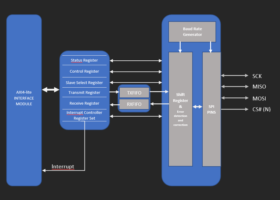
LaRocheNoire Technology (LRN Technology) has designed an SPI interface for aeronautical applications according to aeronautical standards such as DO-254 and AMC20-152A that is fully configurable by the user. Interface configuration involves speed, data transmission and reception verification, activation and deactivation, and data width settings. The figure below offers an overview of the AXI SPI interface for a clearer understanding.
The SPI interface shall own the error detection and correction function. Regarding error detection and correction we chose “Hamming code” as type of error controlling code.
Among various error control codes like VRC, LRC, and cyclic redundancy check, the Hamming code stands out for its efficiency in error detection, ease of implementation, and understanding. While I won’t delve into every error control code here, I’ll shed light on the selected one for our AXI SPI interface’s operation.
As specifed above, we have implemented an error controlling code in the SPI interface and it is “Hamming Code”. It not only provides the detection of a bit error but also identifies which bit is in error. It is a perfect choice for a given length code (data). Its operating principle is as follows: An integer is fixed and each block of m=2^k – k -1 of data is coded by a block of n=2^k – 1 bits, thus adding k bits, known as correction , at certain positions to the block of m bits.
Nearly every embedded system employs the SPI interface. They are especially advantageous due to their easy implementation and used by most manufacturers of sensors and peripherals. However, critical applications demanding stringent standards, like aeronautics (DO-254) and military (MIL-STD), necessitate ensuring error-free transmission of data through communication protocols such as SPI. This is why the AXI SPI Interface incorporates the Hamming corrector to guarantee accurate transmission to the destination.